Interactive Explorer
Coolant Temperature Warning Light Causes and Driver Response

Coolant Temperature Warning Light Causes and Driver Response

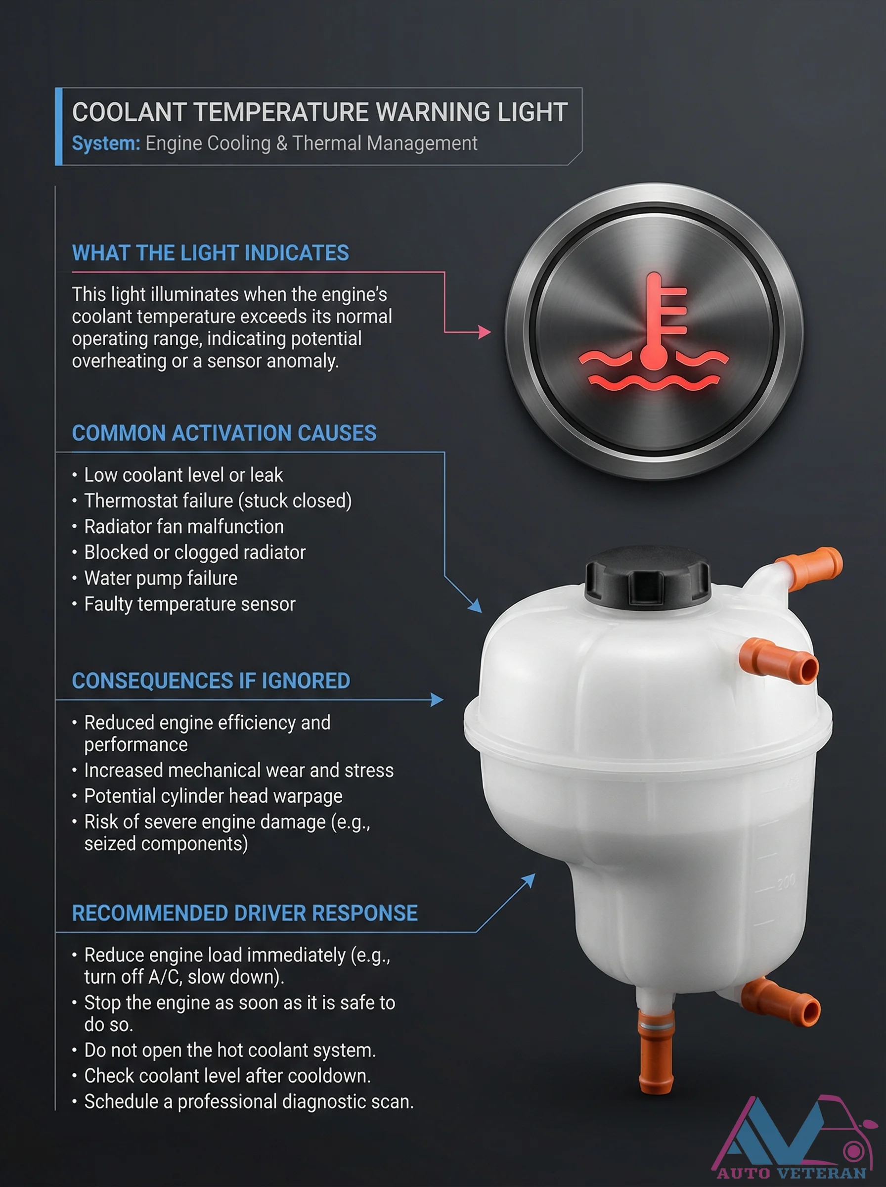
When the coolant temperature warning light activates on your dashboard, it signals that engine coolant has exceeded normal operating parameters, potentially due to low coolant levels, thermostat failure, radiator fan malfunction, clogged radiator, water pump issues, or faulty temperature sensors. Ignoring this warning can lead to reduced engine efficiency, increased mechanical wear, cylinder head warpage, and severe engine damage including seized components. The recommended driver response involves immediately reducing engine load by turning off air conditioning and slowing down, stopping the engine when safe, avoiding opening the hot coolant system, checking coolant levels after cooldown, and scheduling professional diagnostic scanning.

Cooling System Components and Functions Diagram

Cooling System Components and Functions Diagram

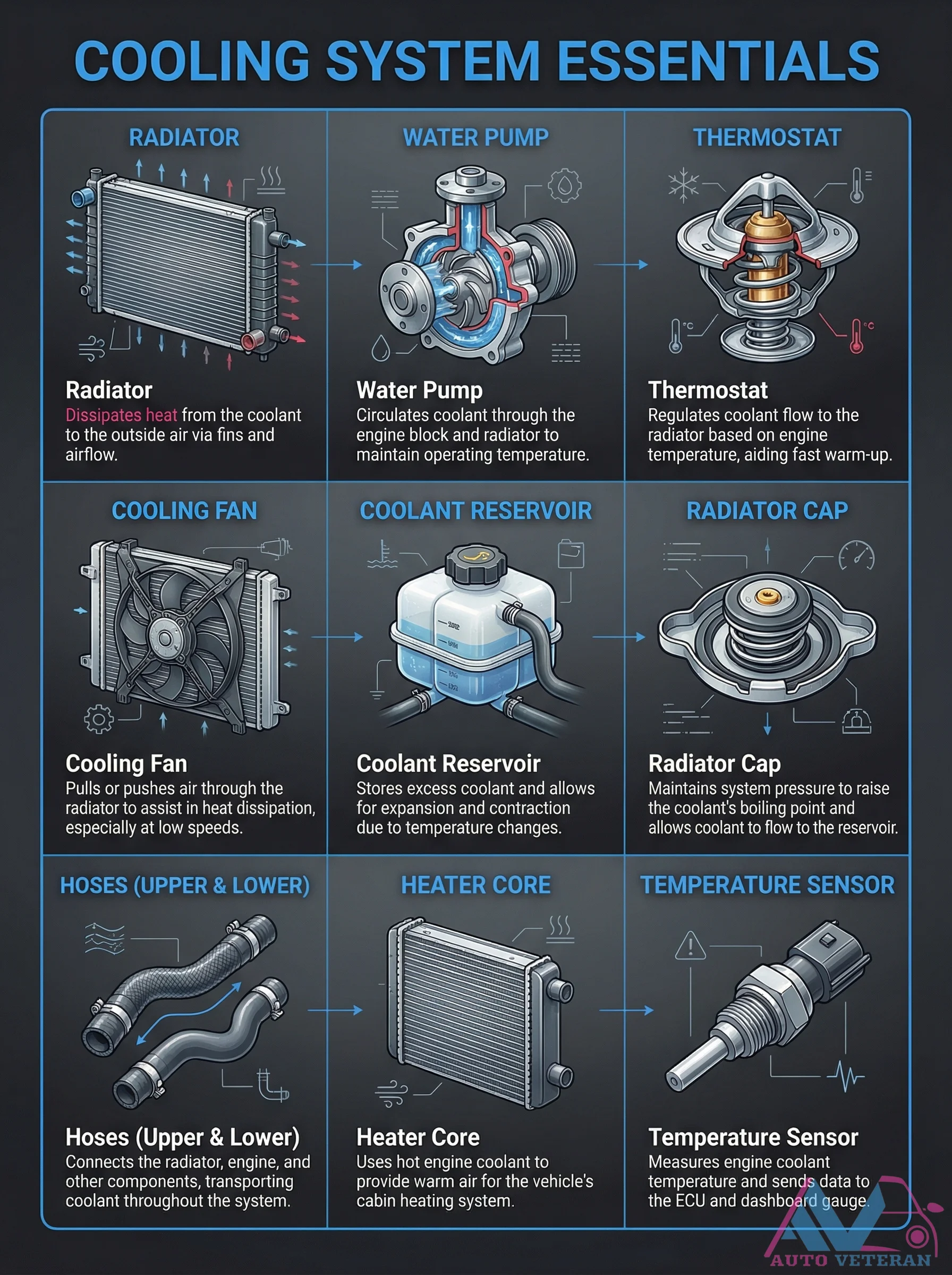
This comprehensive diagram illustrates the essential components of an automotive cooling system and their specific functions. The radiator dissipates heat from coolant to outside air via fins and airflow, while the water pump circulates coolant through the engine block and radiator to maintain operating temperature. The thermostat regulates coolant flow to the radiator based on engine temperature, aiding fast warm up. Additional components include the cooling fan that pulls or pushes air through the radiator, especially at low speeds, the coolant reservoir that stores excess coolant for expansion and contraction, and the radiator cap that maintains system pressure to raise the coolant boiling point. The system also features upper and lower hoses connecting components, a heater core that uses hot coolant for cabin heating, and a temperature sensor that measures coolant temperature for the ECU and dashboard gauge.

Cooling System Essentials Diagram with Components

Cooling System Essentials Diagram with Components

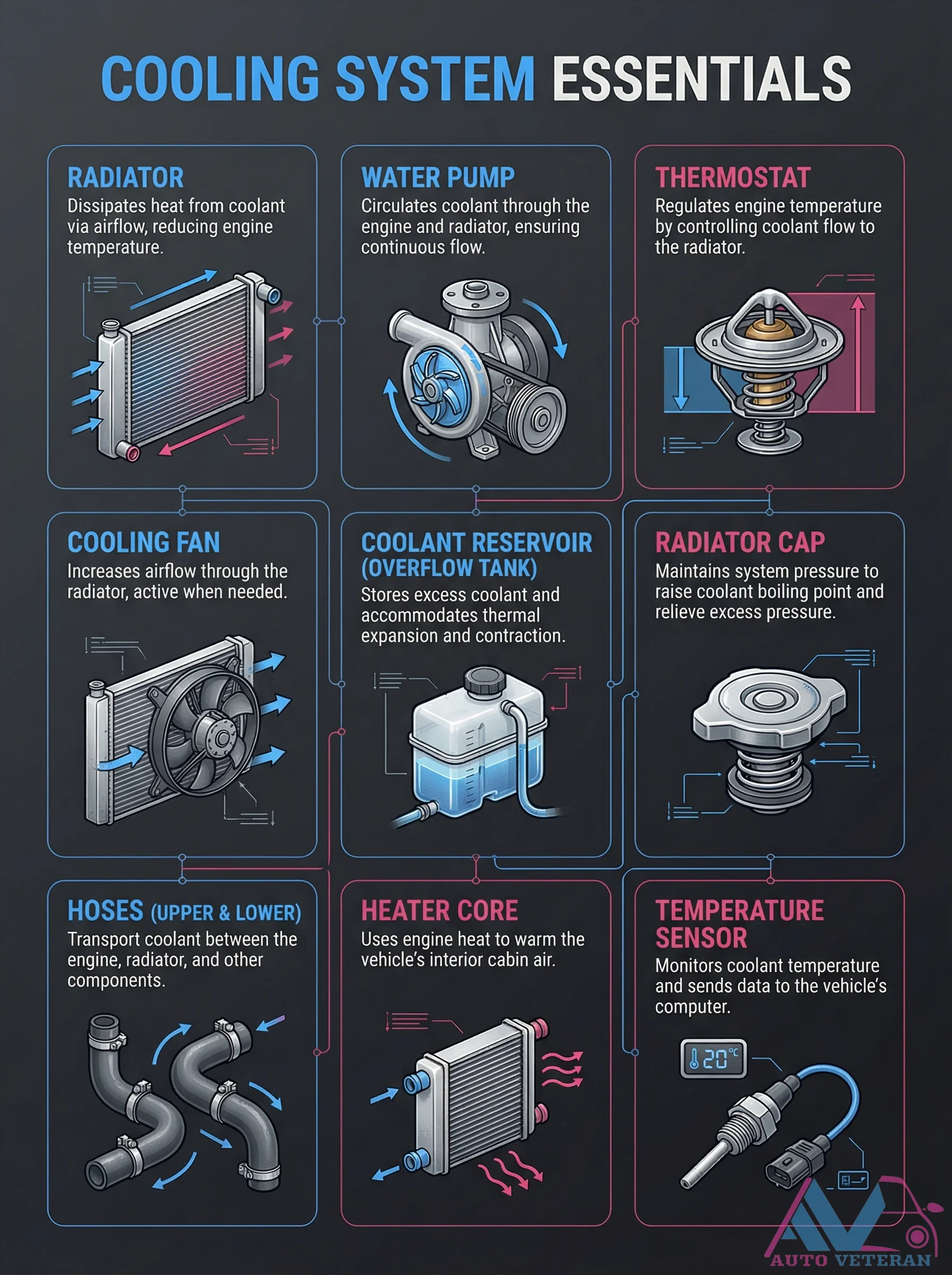
This comprehensive diagram illustrates the essential components of an automotive cooling system, including the radiator, water pump, thermostat, cooling fan, coolant reservoir, radiator cap, hoses, heater core, and temperature sensor. Each component is clearly labeled with its specific function, such as dissipating heat from coolant, circulating coolant through the engine and radiator, regulating engine temperature, increasing airflow through the radiator, storing excess coolant, maintaining system pressure, transporting coolant between components, warming the vehicle's interior cabin air, and monitoring coolant temperature for the vehicle's computer.

Cooling System Step-by-Step Flow Cycle

Cooling System Step-by-Step Flow Cycle

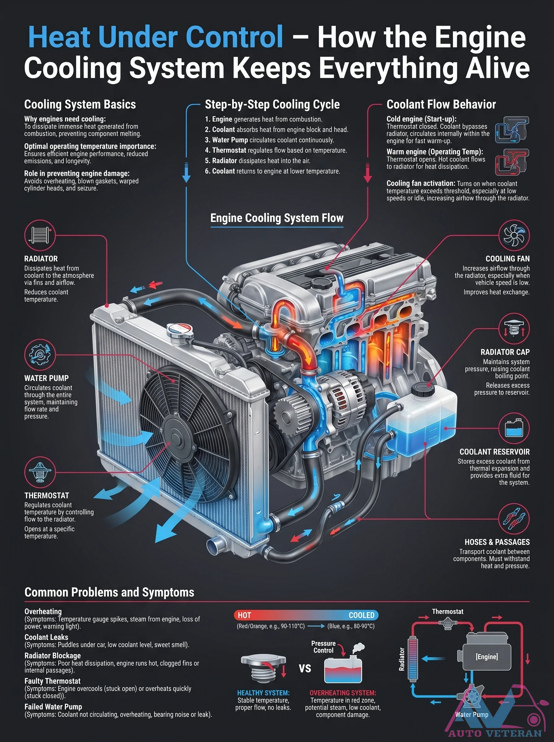
The engine cooling system operates in a continuous cycle: coolant absorbs heat from the block and head, then flows to the radiator where the cooling fan and airflow dissipate that heat. The thermostat regulates flow based on temperature; during cold start it remains closed to warm the engine quickly, then opens to allow full circulation once operating temperature is reached. The water pump drives coolant through passages and hoses, while the radiator cap maintains system pressure to raise the boiling point and prevents boilover. Understanding this flow helps diagnose overheating, leaks, and thermostat failures.

Cooling System Thermal Guardian Operation and Parameters

Cooling System Thermal Guardian Operation and Parameters

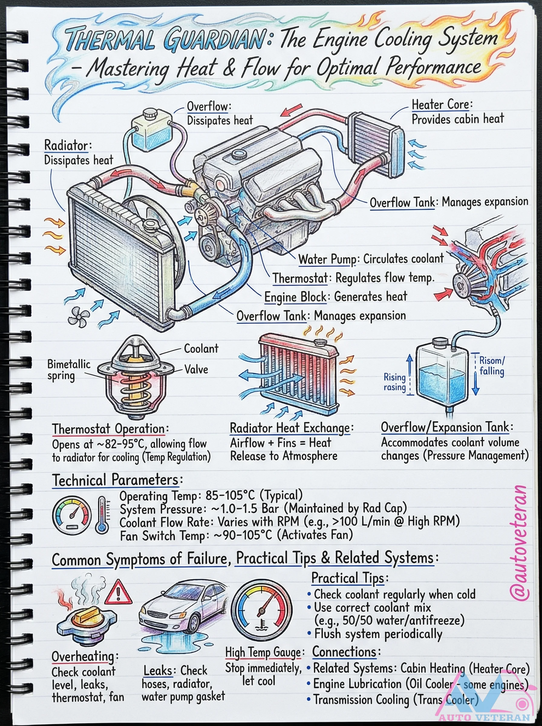
The engine's thermal guardian system expertly manages heat and flow through coordinated components like the radiator, water pump, and thermostat, which opens at 82-95°C to regulate coolant flow. Operating within 85-105°C at 1.0-1.5 bar pressure, with flow rates up to 2100 L/min at high RPM, it prevents overheating while supporting cabin heating and related systems. Common failure symptoms include leaks and overheating, emphasizing the need for regular coolant checks and proper 50/50 antifreeze mixtures.

Correct Wheel Bolt Tightening Order

Correct Wheel Bolt Tightening Order

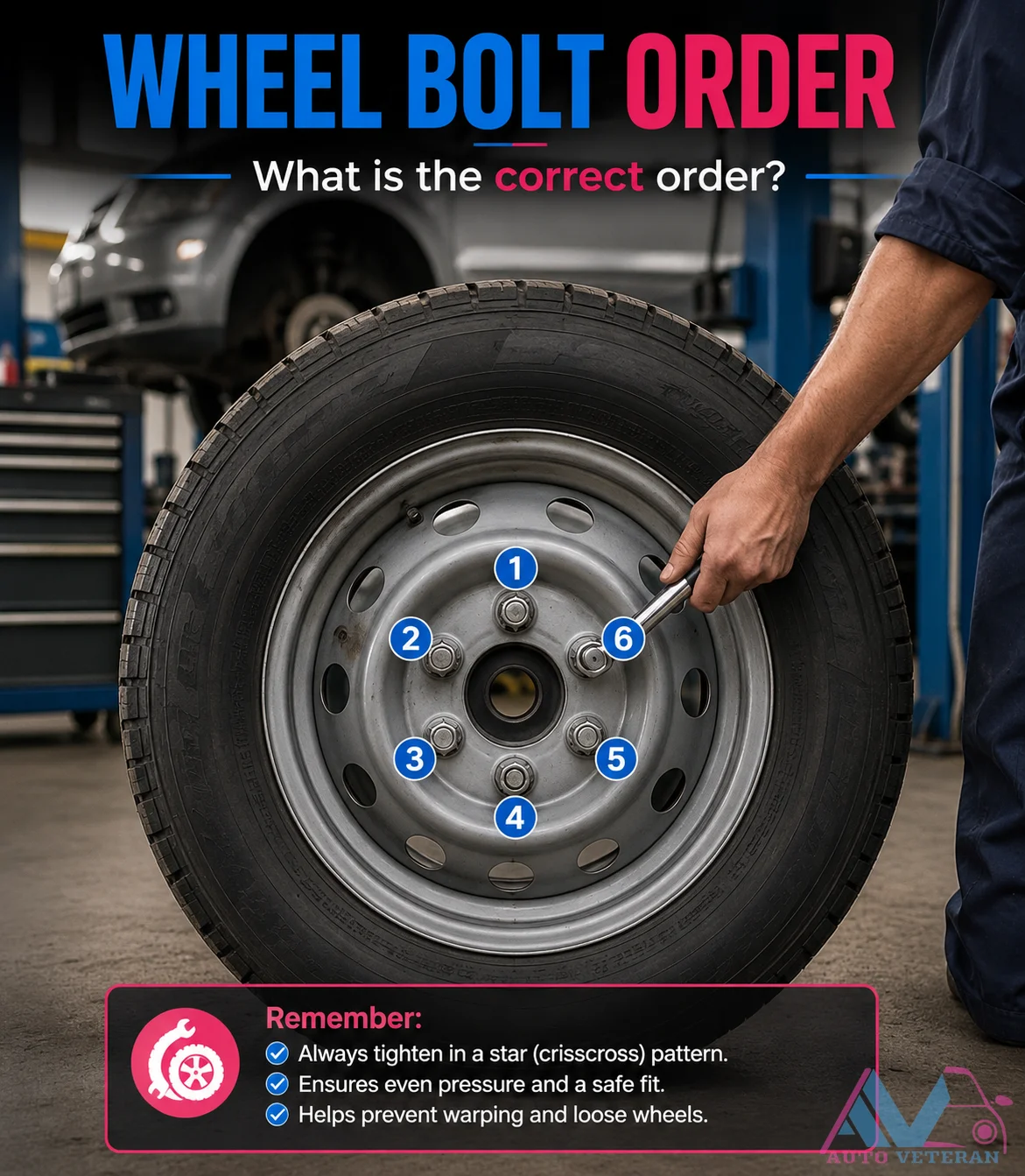
Always tighten your wheel bolts or lug nuts in a star (crisscross) pattern to apply even pressure across the wheel mounting surface. This method prevents warping the brake rotor or drum, ensures the wheel seats evenly, and keeps the fasteners properly torqued for a safe and secure fit. Skipping this order can lead to loose wheels, vibration, and potential failure on the road.

Cranks No Fire Diagnostic Flowchart

Cranks No Fire Diagnostic Flowchart

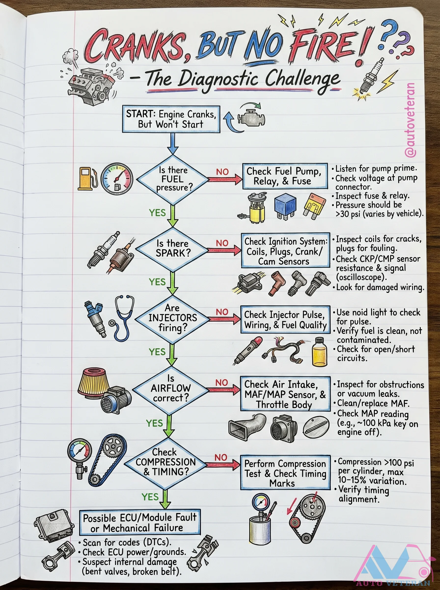
This troubleshooting guide walks through the systematic process for an engine that cranks but refuses to start. Starting with verifying no fuel pump prime and no spark, each branch tests fuel pressure, ignition system components like coils and crank/cam sensors, injector pulse with a noid light, and air intake integrity including MAF/MAP sensor readings. The chart ends with compression and timing checks to rule out mechanical failures or ECU faults, covering every angle from simple fuses to internal engine damage.

Crankshaft Cross-Plane vs Flat-Plane Designs

Crankshaft Cross-Plane vs Flat-Plane Designs

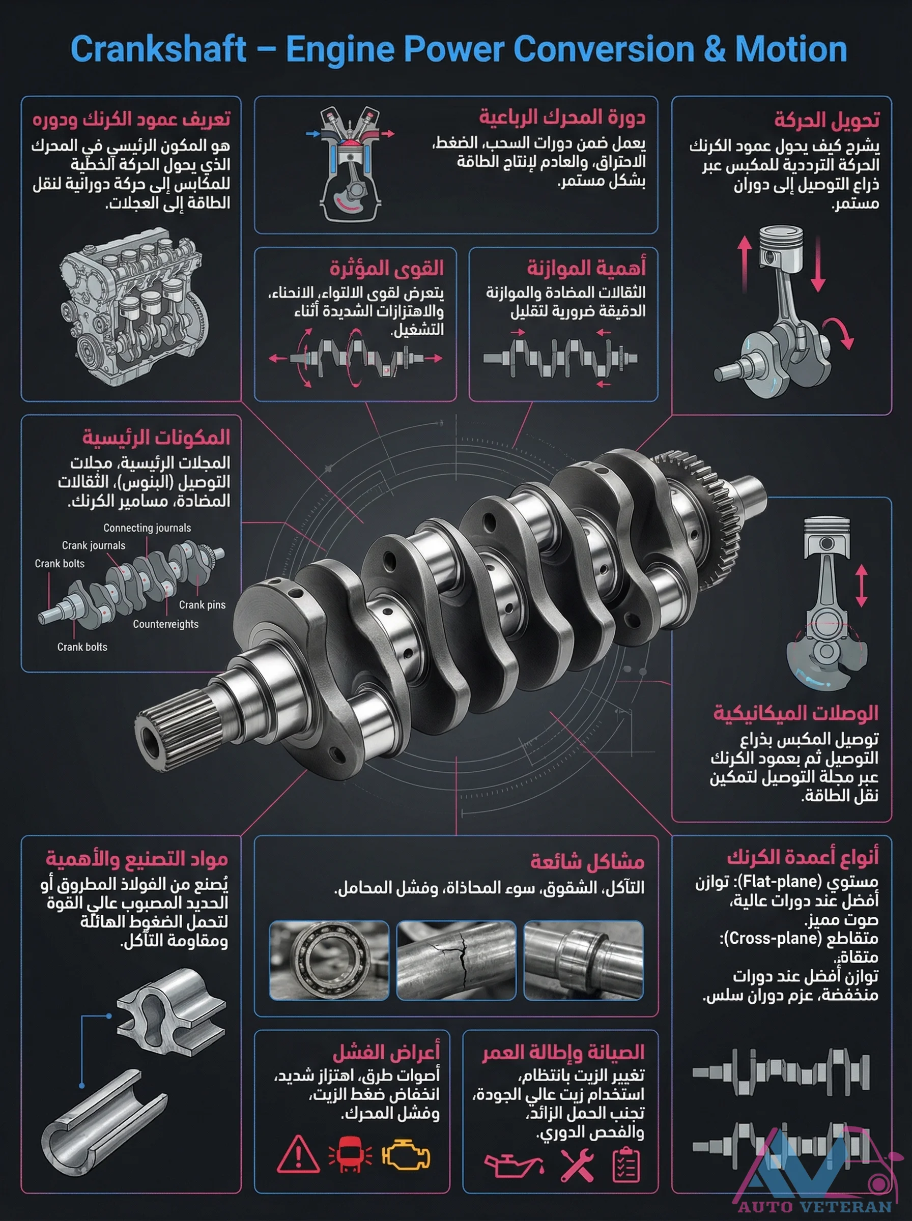
The crankshaft converts piston motion into rotational power, with two primary designs offering distinct characteristics. Cross-plane crankshafts provide superior balance and smooth operation, making them ideal for street vehicles and torque-focused applications. Flat-plane crankshafts deliver higher revving capability and quicker throttle response, favored in high-performance racing engines. Understanding these differences helps in selecting the right configuration for specific engine requirements, balancing factors like vibration, power delivery, and application needs.

Crankshaft Journal Types and Failure Modes

Crankshaft Journal Types and Failure Modes

Crankshafts feature main journals and rod journals that connect to engine bearings, with counterweights balancing rotational forces. Common failure modes include wear on journals leading to knocking sounds, cracks from stress, misalignment causing vibration, overloading, bearing failure, and eventual engine failure. Flat plane and cross plane crankshaft designs differ in journal arrangement and performance characteristics.

Crankshaft Operation Forces Balancing and Failure Symptoms

Crankshaft Operation Forces Balancing and Failure Symptoms

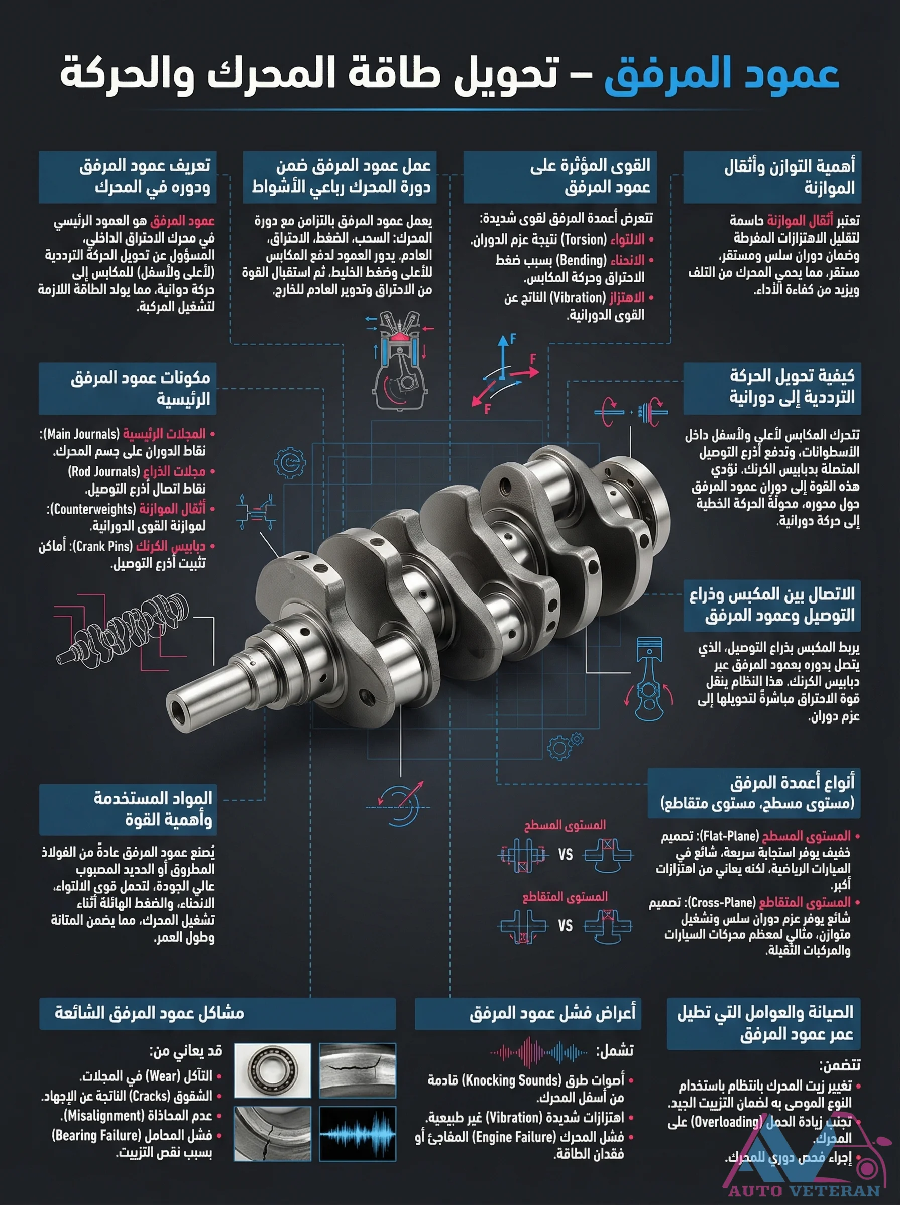
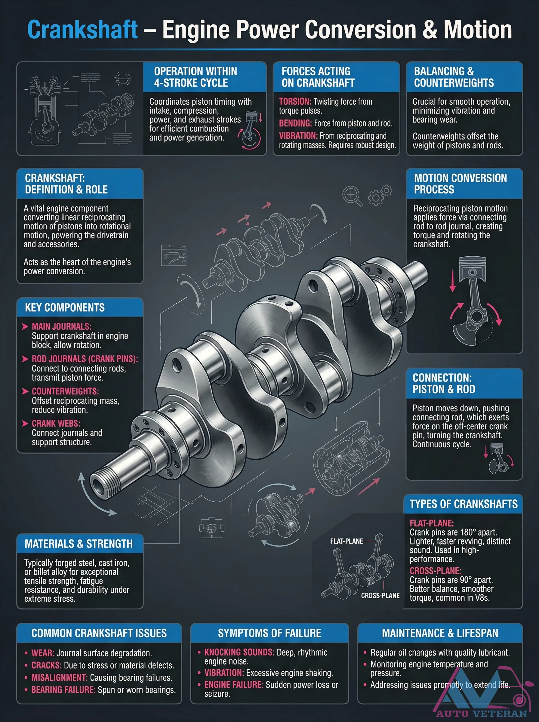
The crankshaft serves as the heart of an engine's power conversion system, transforming the linear reciprocating motion of pistons into rotational energy that drives the drivetrain and accessories. This complex component must withstand multiple forces including torsion from torque pulses, bending from piston and rod forces, and vibration from reciprocating masses. Counterweights strategically offset piston and rod weight to minimize vibration and bearing wear, while robust materials like forged steel or billet alloy provide exceptional tensile strength and fatigue resistance. Common failure symptoms include deep rhythmic knocking sounds, excessive engine vibration, and sudden power loss or seizure, often resulting from journal wear, cracks due to stress, misalignment, or bearing failure. Proper maintenance with regular oil changes and prompt issue resolution can significantly extend crankshaft lifespan.

Crankshaft Operation Forces Balancing and Types

Crankshaft Operation Forces Balancing and Types

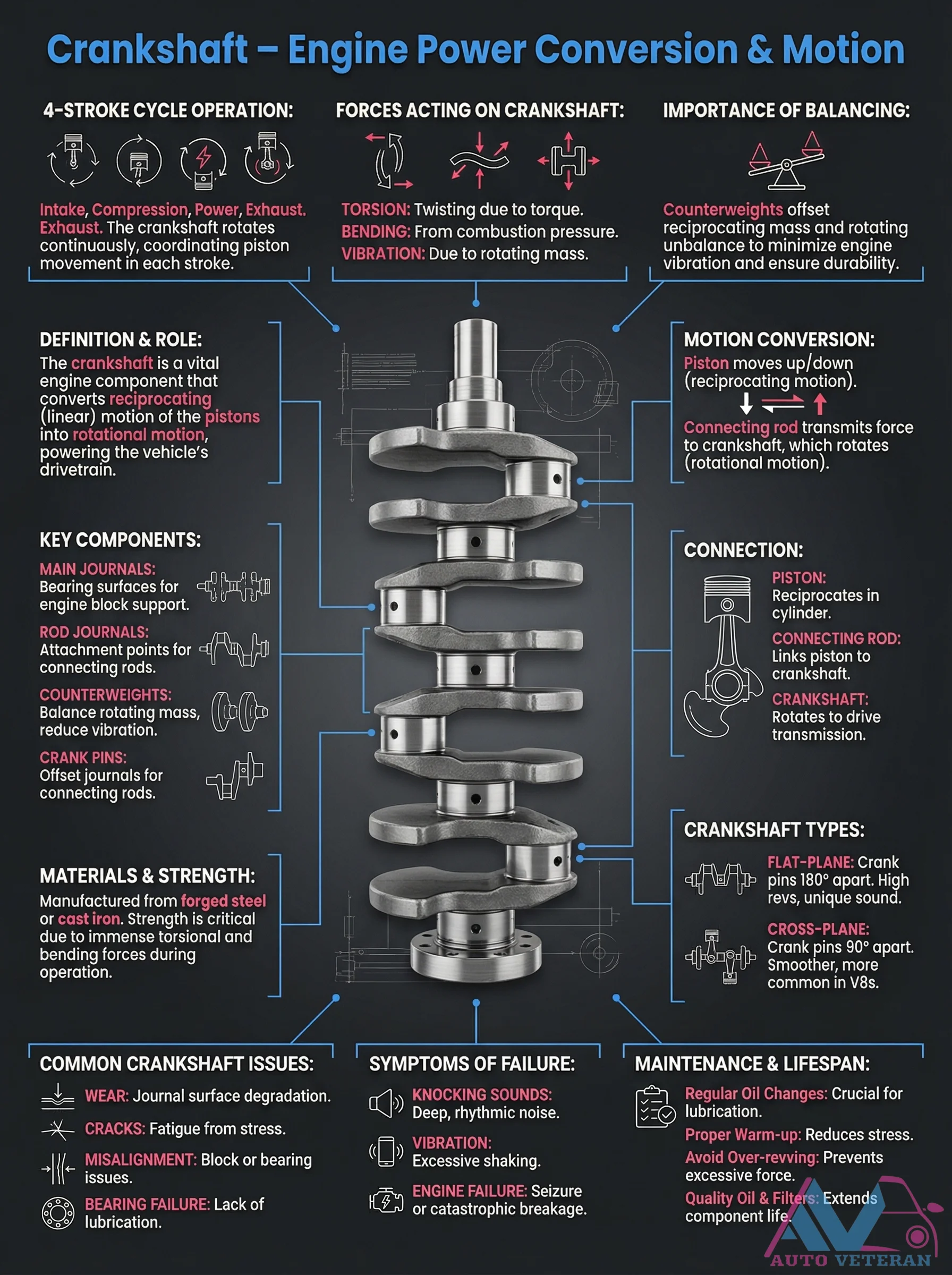
The crankshaft serves as the heart of engine power conversion, transforming the reciprocating motion of pistons into rotational force that drives the vehicle. This intricate component faces immense torsional and bending forces during the four stroke cycle operation, requiring precise balancing through counterweights to minimize vibration and ensure durability. Key elements include main journals for block support, rod journals for connecting rod attachment, and crank pins with specific offset designs. Two primary crankshaft types exist: flat plane configurations with crank pins 180 degrees apart for high revving performance and distinctive sound, and cross plane designs with 90 degree spacing for smoother operation commonly found in V8 engines. Common issues include journal wear, cracks from stress fatigue, bearing failure from inadequate lubrication, and misalignment problems, with symptoms manifesting as deep knocking sounds, excessive vibration, or catastrophic engine seizure. Proper maintenance through regular oil changes, quality lubrication, proper warm up procedures, and avoiding over revving are critical for extending the crankshaft's lifespan and preventing premature failure.

Crankshaft Piston Reciprocating Motion

Crankshaft Piston Reciprocating Motion

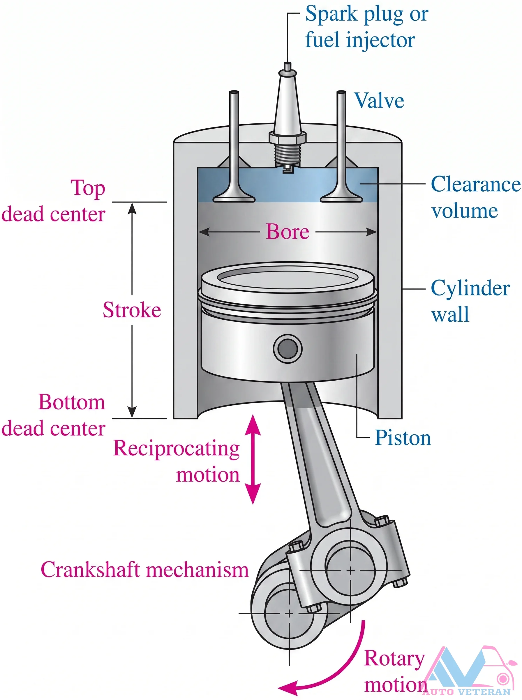
This technical illustration maps the core of internal combustion: the crankshaft mechanism converting piston reciprocating motion into rotary motion. It highlights key dimensions like bore, stroke, valve top clearance, and dead center positions (TDC and BDC) along with cylinder wall geometry, essential for understanding engine displacement and compression.

Critical Engine Sensors Failure Symptoms Guide

Critical Engine Sensors Failure Symptoms Guide

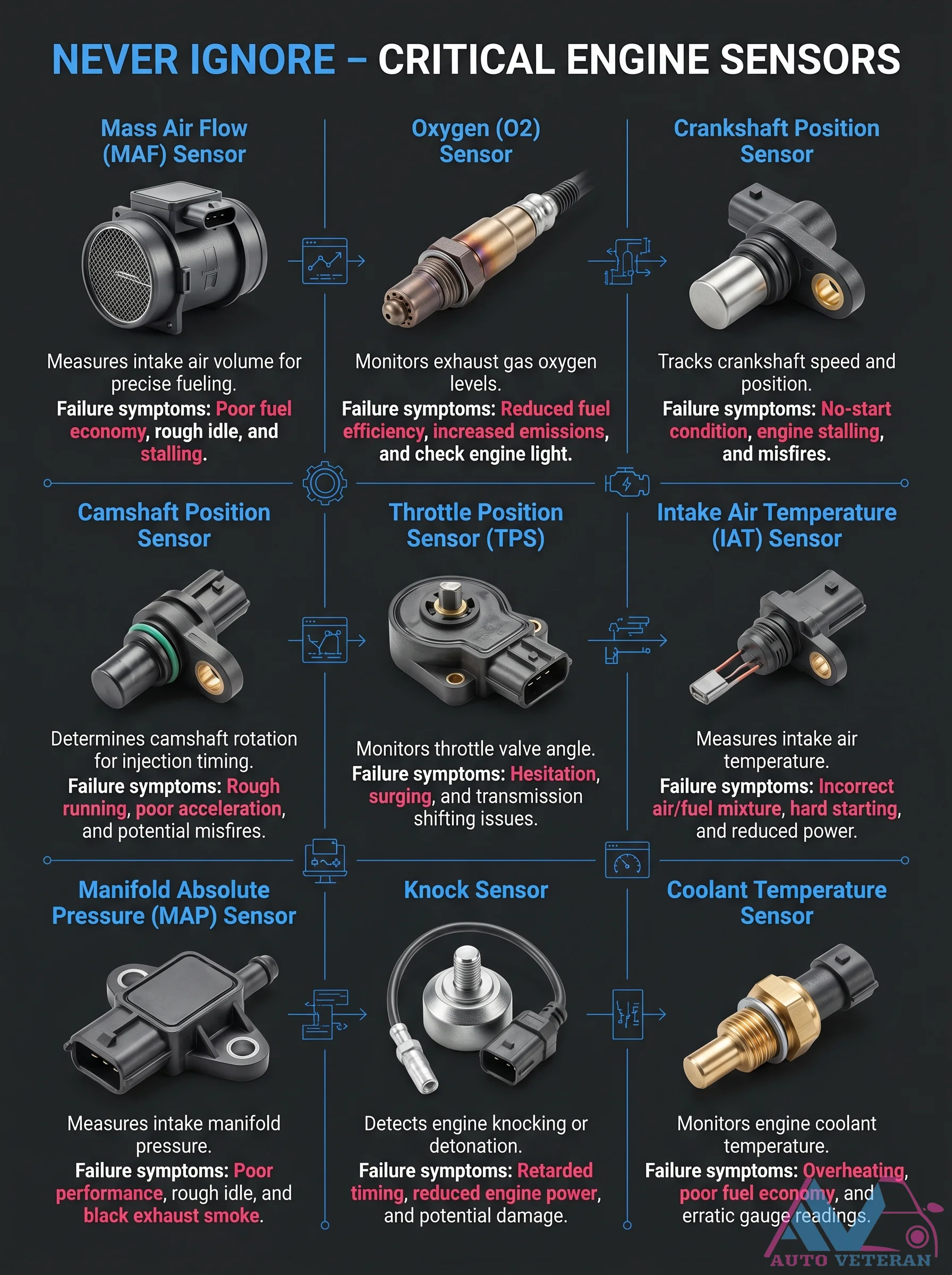
This comprehensive guide details the specific failure symptoms for six essential engine sensors: the Mass Air Flow sensor causing poor fuel economy, rough idle, and stalling; the Oxygen sensor leading to reduced fuel efficiency and increased emissions; the Crankshaft Position sensor resulting in no start conditions and engine stalling; the Camshaft Position sensor causing hesitation, surging, and transmission shifting issues; the Throttle Position sensor creating rough running and poor acceleration; and the Knock sensor triggering retarded timing and reduced engine power. Understanding these distinct symptoms helps diagnose common engine performance problems accurately.

CV Axle Assembly Failure Symptoms and Service Notes

CV Axle Assembly Failure Symptoms and Service Notes

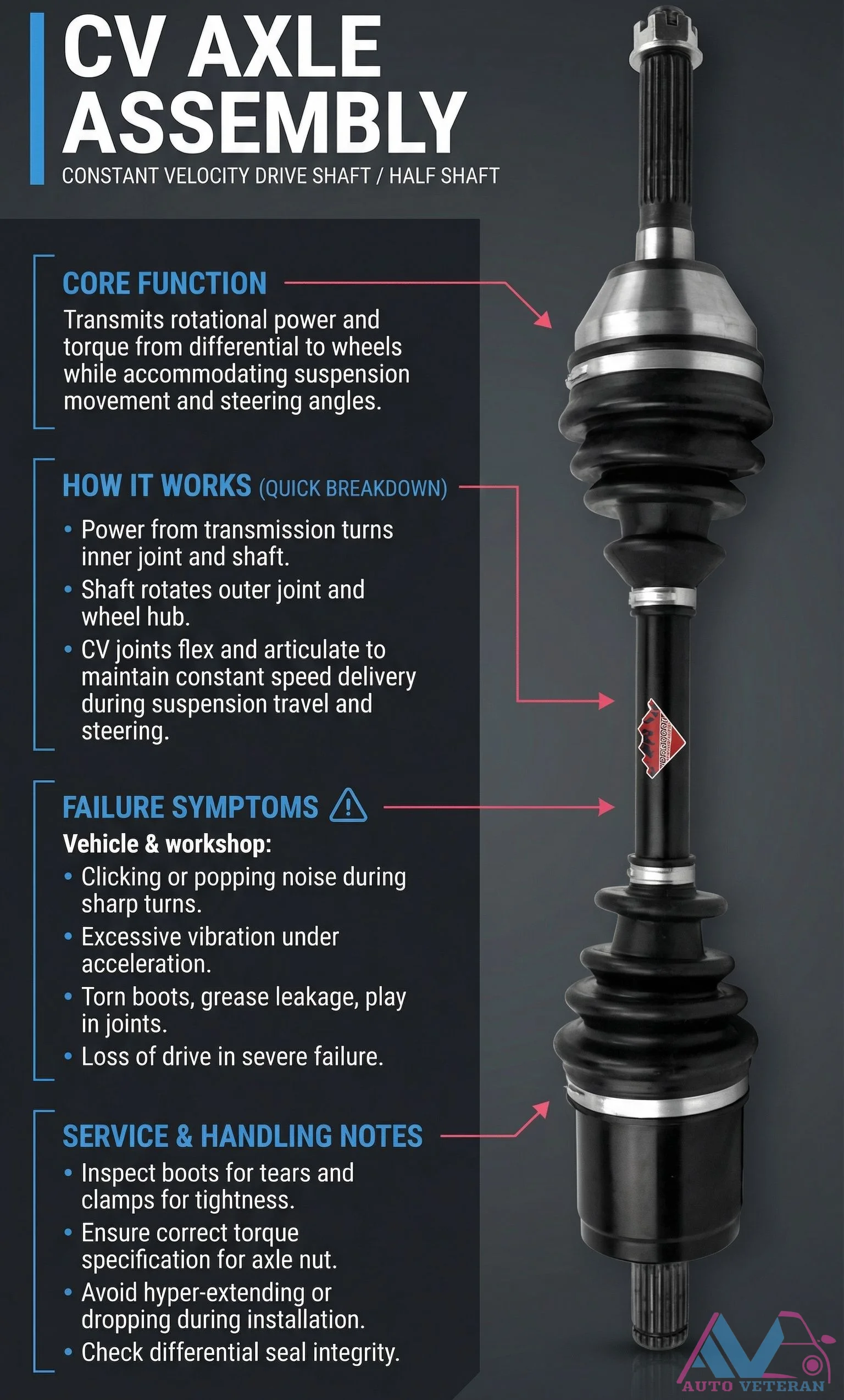
A Constant Velocity Axle Assembly transmits rotational power from the differential to the wheels while accommodating suspension movement and steering angles. Common failure symptoms include clicking or popping noises during sharp turns, excessive vibration under acceleration, torn boots with grease leakage, and play in the joints. Proper service requires inspecting boots for tears and clamps for tightness, ensuring correct torque specifications for the axle nut, avoiding hyper-extending or dropping during installation, and checking differential seal integrity to prevent severe drive loss.

CV Axle Shaft Failure Symptoms and Inspection Tips

CV Axle Shaft Failure Symptoms and Inspection Tips

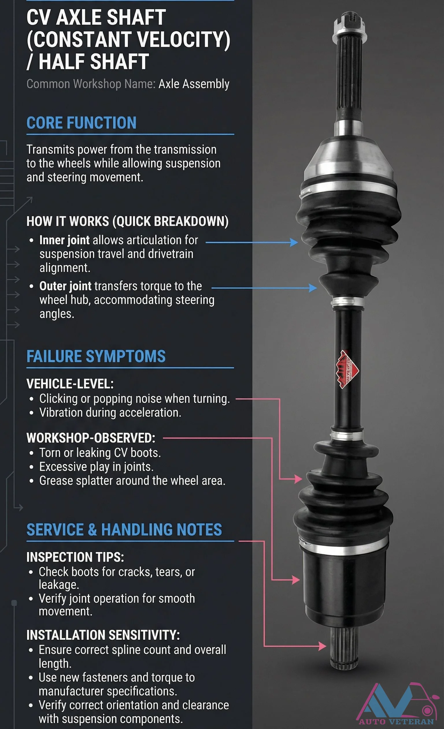
A CV axle shaft, also known as a half shaft or axle assembly, transmits power from the transmission to the wheels while accommodating suspension and steering movement. Common failure symptoms include clicking or popping noises when turning, vibration during acceleration, torn or leaking CV boots, excessive play in joints, and grease splatter around the wheel area. For inspection, check boots for cracks, tears, or leakage, and verify joint operation for smooth movement. Proper installation requires ensuring correct spline count and overall length, using new fasteners torqued to manufacturer specifications, and verifying correct orientation and clearance with suspension components.

Link copied!